Advances in Electronic Packaging - 1997, EEP-Vol. 19-1,
InterPACK '97, Kohala Coast, Hawaii
June 15-19, 1997, 957-962.
Russell S. Peak (1), Robert E. Fulton (1,3), Suresh K. Sitaraman (2,3)
(1) Engineering Information Systems Laboratory, eislab.gatech.edu
(2) Computer Aided Simulation of Packaging Reliability Laboratory
(3) School of Mechanical Engineering
Georgia Institute of Technology
Atlanta, Georgia
In the DARPA-sponsored TIGER collaborative engineering demonstration, a large manufacturer provides its suppliers early PWA/B design information in a neutral format (AP210 DIS - the draft STEP PWA/B product model standard). Suppliers use the TIGER Toolset at an Internet-based engineering service bureau to perform a variety of design checks, including design-for-manufacturability and thermomechanical analysis. This paper overviews the latter capabilities with an emphasis on the CAD/CAE integration techniques utilized.
Examples include warpage analysis modules which PWB fabricators employ to evaluate designs in a highly automated manner. This system is the first known usage of STEP AP210 DIS to drive engineering analysis (in Ansys) using design information from a commercial board layout tool (Mentor Graphics). A recent demonstration shows these techniques bring unique supplier expertise to an integrated product team, enabling timely, cost-saving design improvements.
APM - Analyzable product model
IPT - Integrated product team
PWA - Printed wiring assembly (with components)
PWB - Printed wiring board (without components)
SME - Small-to-medium-sized enterprise (supplier)
AP210 - ISO STEP std. for PWA/B product models
TIGER - Team InteGrated Electronic Response
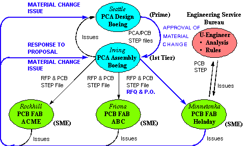
The DARPA-sponsored TIGER project (Team Integrated Electronic Response) demonstrates advanced engineering collaboration between primes and suppliers using standards-based design, analysis, and manufacturing tools [TIGER, 1997]. In the TIGER scenario (Fig. 1), a Prime releases early printed wiring assembly/board (PWA/B) design information to its Assembly Factory (1st Tier Manufacturer) for design feedback. The Assembly Factory in turn assigns several of its PWB suppliers to the integrated product team (IPT) and sends them PWB design information in a standard STEP format [Peak and Tamburini, 1997], along with request for proposals (RFPs). One of these small-to-medium-sized enterprises (SMEs) uses the TIGER toolset via an Internet-based engineering service bureau to perform a variety of process-specific design checks, including design-for-manufacturability (DFM) and thermomechanical analysis. Suppliers feedback design improvement suggestions via a Negotiation Facility.

This TIGER scenario has been tested with Boeing and Holaday Circuits as a representative prime and supplier, respectively. Other team members are Arthur D. Little (ADL), the Atlanta Electronic Commerce Resource Center (AECRC), Georgia Tech, International TechneGroup Inc. (ITI), and South Carolina Research Authority (SCRA, the program lead).
This paper overviews this prime-supplier interaction with an emphasis on the product model-driven analysis capabilities, the underlying CAD/CAE integration techniques, and their demonstration using thermomechanical PWA/B applications.
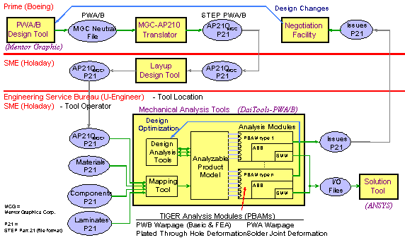
Fig. 2 summarizes the architecture by which an SME can perform product data-driven thermomechanical analyses using TIGER Tools located at an engineering service bureau. Other larger companies (such as Boeing in this scenario) may choose to install these tools locally and perform analyses in a similar manner.
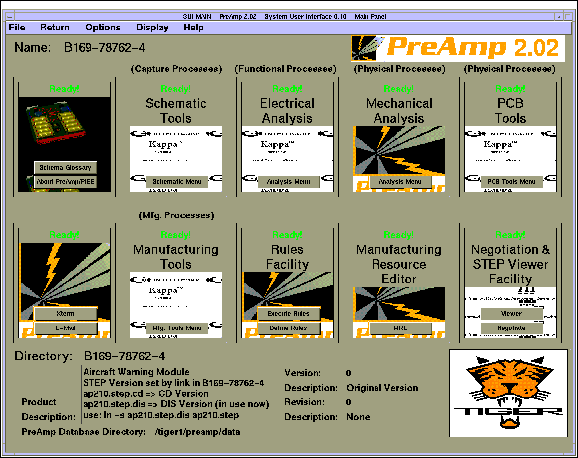
The TIGER system user interface (SUI) manages design versions and inter-tool information exchange (Fig. 3). From the SUI, Prime designers at Boeing complete a preliminary PWA design in the Mentor Graphics Corp. board layout tool. They export it as a neutral file, and then convert this file to a STEP AP210 file [Hines, 1996]. PWB fabrication engineers at Holaday Circuits receive the STEP file after an electronic RFP process that formalizes them as members of the IPT.
As the STEP file contains PWB design details in a neutral form, fabrication engineers can use it to drive internal tools such as layup design. In the TIGER case, they upload this design file to an engineering service bureau (U-Engineer) over the Internet using a secure protocol [Scholand et al. 1997]. At the bureau they have access to TIGER Tools similar to those located at the Prime and Assembly Factory, including thermomechanical analysis modules that they execute themselves in a highly automated manner.
From the TIGER SUI, they launch DaiTools-PWA/B [EIS Lab, 1997], read in the AP210 file, and run these analysis modules, including PWB warpage and plated through hole deformation. If the results indicate a potential problem or design improvement opportunity, the fabrication engineers instruct DaiTools to create an issue (containing a summary of results from the analysis) and submit it to the Negotiation Facility [TIGER, 1997]. This tool coordinates IPT membership and tracks issues, comments, and resolutions to aid collaborative design evaluation and improvement. The Prime designers change the design based on this feedback, and re-issue design data to the Assembly Factory and SMEs. The SMEs can re-run analyses in the same manner if needed, thus illustrating the iterative collaborative engineering loop enabled by TIGER (Fig. 2).
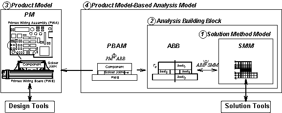
Fig. 4 summarizes the multi-representation architecture (MRA) [Peak et al. 1995] used in TIGER to integrate PWA/B design models with analysis models in a flexible, modular manner. Solution method models (SMMs) are object-oriented wrappers around solution tools (e.g., FEA systems like Ansys) that utilize an agent-based framework to obtain analysis results in a highly automated manner. Analysis building blocks (ABBs) are a representation of engineering analysis concepts with high semantic content. ABBs generate SMMs based on solution technique-specific considerations such as symmetry and mesh density. Product models (PMs) represent design-oriented details, providing a common stepping stone to design tools and supporting idealizations for analysis models [Tamburini et al. 1996, 1997]. Finally, product model-based analysis models (PBAMs, a.k.a. analysis modules) are a new type of engineering model that explicitly represent the associativity between analysis models and design models (i.e., ABBs and PMs).
The MRA routinization process, a knowledge capture technique [Peak et al. 1996], has been employed in TIGER to create analysis modules/PBAMs like those in the PWB warpage catalog (Figs. 7, 8). The primary input to this process for FEA-based modules has been parameterized finite element files populated with representative values. Routinization transforms these files into templates that can be fed with product data from a wider range of PWB designs. DaiTools-PWA/B is a specialized CAE tool in which these PWA/B-specific analysis modules have been implemented using a general design-analysis integration toolkit [Peak et al. 1995].
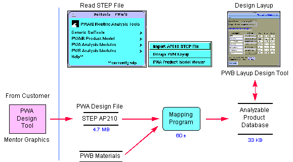
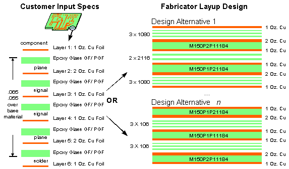
After fabrication engineers have uploaded a PWB STEP file to the engineering service bureau, Fig. 5 shows how DaiTools reads in the STEP file. This step combines it with other information to form an analyzable product model (APM) [Tamburini et al. 1996, 1997] that includes idealizations to drive a variety of analysis modules. As layup details affect PWB thermomechanical behavior, fabrication engineers first design a layup, selecting specific laminates, prepregs, and copper foils to physically realize the requirements specified by the Prime designers in the AP210 model (Fig. 6).
By selecting a formula-based Thermal Bending Model from
a catalog of PWB warpage modules, the user can perform quick checks
and design comparisons (Fig. 7). This module has evolved from
work by Scholand and is described by Peak, Scholand, et al. [1996]
to illustrate the routinization process. The idealized attribute
termed coefficient of thermal bending,![]() ,
is a lumped material property of the total layup, and is supported
in the APM as a weighted sum of individual stratum properties
[Tamburini et al. 1997].
,
is a lumped material property of the total layup, and is supported
in the APM as a weighted sum of individual stratum properties
[Tamburini et al. 1997].
If more accurate results are desired, fabrication engineers select an FEA-based Plane Strain Warpage Model which uses idealized attributes from the APM for each stratum (Figs. 7, 8). This type of model is based on work by the CASPaR Lab [Dunne et al. 1997], plus extensions to consider the effects of material variations (so that warpage deformation of symmetric layups can also be analyzed).
Fig. 8 shows an instance of this plane strain model that has been employed for routine analysis [Peak et al. 1995]. The top left region lists two other types of analysis modules available in the PWB warpage catalog. As with the other warpage modules, the user first selects the PWB object to analyze (which comes from Mentor Graphics via AP210, plus the addition of layup details). Then he or she enters temperatures of interest (e.g., for the lamination process as here). Finally, the user selects <calculate> to see deformations on a local PWB section. This module then automatically extracts idealized attributes from the APM and creates a finite element job file. It submits the job to an FEA tool (Ansys in this case) for automated execution using a technique demonstrated previously with solder joint deformation modules [Peak et al. 1993, 1995]. The user receives results back in PWB-specific terms that are then checked against allowables.
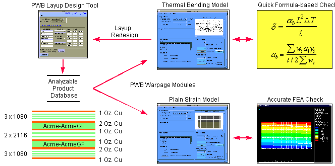
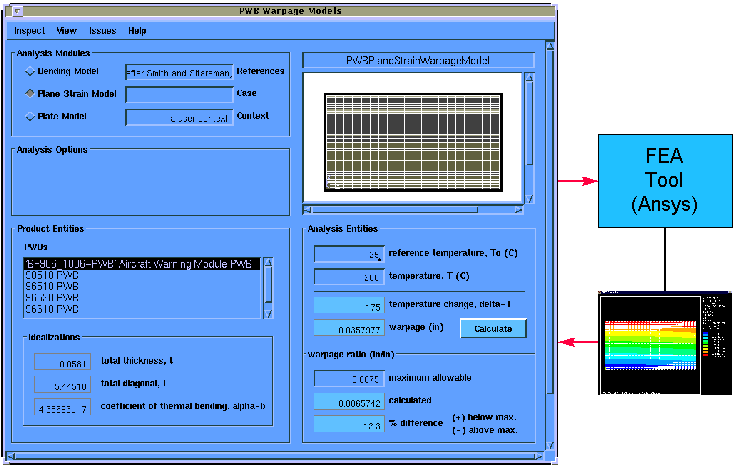
DaiTools contains a layup tool (Figs. 5, 7) as a representative design idealization tool that is tightly integrated for rapid, iterative analysis. Fabrication engineers can design a variety of layups and evaluate them with both warpage modules (Figs. 7, 8) and other PWB modules. This product data-driven analysis capability automates tedious data inputs and model creation, enabling a convenient form of manual design optimization. Cimtalay et al. [1996] describe steps towards an automated optimization technique that uses analysis modules such as these.
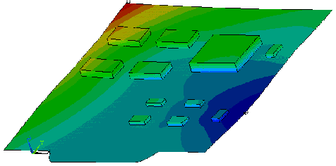
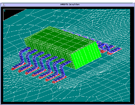
Other examples in TIGER include previous solder joint deformation and fatigue models [Peak et al. 1993; 1995], as well as initial routinization of recent plated-through hole models [Sizemore and Sitaraman, 1995]. Preliminary models of PWA warpage (which include components) have been developed in TIGER by adding an APM front end to the parametric FEA modeling technique described by Zhou et al. [1997]. A PWA layout can be altered in commercial design tools and used to generate complex finite element models. For example, the designer can move components in Mentor Graphics, feed the new design into DaiTools via STEP AP210, and have it automatically create models like Figs. 9 and 10.
On Feb. 21, 1997 the TIGER Team conducted the premier demonstration of the overall scenario depicted in (Fig. 1) [TIGER, 1997]. Each IPT member was represented in the SCRA auditorium at Charleston SC: Prime designer; 1st Tier manufacturing engineer and procurement assistant; and SME fabrication engineer and salesman. With each person physically located at separate workstations/PCs, design and business information was exchanged some 20 times during the hour long demo. From his PC, the fabrication engineer uploaded the live, Mentor Graphics-originated AP210 model to U-Engineer (the self-service analysis bureau physically located in Atlanta). He then performed warpage analysis iterations over the Internet as illustrated above (Figs. 2, 7), including automated Ansys model creation displayed in real time via X Windows.
The same scenario has also been performed by Boeing and Holaday personnel while physically located in Seattle WA, Irving TX, and Minnetonka MN, confirming that TIGER is truly "a STEP towards printed circuit design iterations in about an hour".
The emphasis of this project has been on information integration to support prime-supplier collaborative engineering, with a Georgia Tech focus on design-analysis integration. Though representative for this latter purpose, some of the analysis models need refinement to improve the value of their results for routine engineering usage. For example, given a refined PWB warpage model that consistently gives good results, in all likelihood it can be routinized and turned into an analysis module like those highlighted here (Figs. 7, 8).
TIGER has helped both evolve the MRA design-analysis integration technique and confirm its basic thrusts. The APM representation [Tamburini et al. 1996, 1997] has crystallized during TIGER and added the critical link to commercial design tools such as Mentor Graphics. The parametric technique [Zhou et al. 1997] brings advanced modeling capabilities to the table that are not practical with typical automeshing techniques. The modularity and diversity supported by the PBAM representation [Peak et al. 1995] have been confirmed by the routinization of examples beyond solder joint fatigue.
The TIGER experience has emphasized the importance of including suppliers in early design evaluations, and the fact that they often do some design themselves. Their expertise can enable design checks that are more precise than those typically done by primes. For example, the warpage analysis scenario utilizes the detailed PWB layup designed by fabrication engineers, as well as their precise knowledge of PWB materials and lamination conditions.
However, TIGER has also highlighted the formidable barriers against suppliers performing such analyses, including CAE tool costs, analysis model development and awareness, and ease-of-use. Thus the Internet-based engineering service bureau was born [Scholand et al. 1997], with its emphasis on self-service analysis - a capability made possible by the product data-driven techniques described. Note, too, that such integration tools can be installed locally in larger companies where these same barriers exist (especially the latter two).
The TIGER collaborative engineering scenario demonstrates how a large manufacturer provides suppliers early PWA/B information in a standard format for early design feedback. This paper highlights how PWB fabrication engineers utilize this design model and their expertise to drive thermomechanical analyses such as PWB warpage in a highly automated manner.
The CAD/CAE integration techniques utilized to create representative analysis modules have been extended and confirmed in TIGER. Accomplishments include the world's first usage of AP210 DIS (the STEP draft standard for PWA/Bs) to automatically drive finite element analyses (in Ansys) - all using live data that originates in a commercial circuit board layout tool (Mentor Graphics).
A demonstration Internet-based engineering bureau delivers these capabilities to suppliers on a basis ranging from self-service (for highly automated routine analyses) to full-service (for challenging new analyses). This paradigm provides suppliers advanced capabilities without requiring expensive in-house tools and analysis expertise. As seen at a recent live demonstration, the advantage of TIGER techniques is the effective inclusion of suppliers in the product team, enabling timely, cost-saving design improvements.
This work has been funded under the DARPA TIGER Program [TIGER, 1997]. The design-analysis integration techniques and prototypes were originally sponsored by the Georgia Tech Mfg. Research Center.
Portions emphasized in this paper resulted from the dedicated effort of the whole Georgia Tech group, primarily:
EIS Lab: Selcuk Cimtalay, Robert Fulton, Russell Peak, Andrew Scholand, Diego Tamburini, and Wen Zhou
CASPaR Lab: Jill Conley, Suresh Sitaraman, Jorg Sizemore, and Kyle Smith.
We appreciate the interactions and contributions of the other 20+ team members and support staff who made the total collaborative engineering scenario a reality. In particular, Jeff Lewis (Holaday Circuits) provided insights on PWB layup design, and Lynwood Hines (SCRA) helped us work with an early undocumented version of STEP AP210 DIS. We are grateful for the support of Leo Plonsky (DARPA/ONR) and his instrumental thoughts that evolved into the TIGER engineering service bureau paradigm.
Cimtalay, S.; Peak, R. S.; Fulton, R. E. (1996) Optimization of Solder Joint Fatigue Life Using Product Model-Based Analysis Models. Application of CAE/CAD to Electronic Systems, EEP-Vol.18, Agonafer, D. et al. eds., ASME Intl. Mech. Engr. Congress & Expo., Atlanta, 47-53.
Dunne, R., Smith, K., Sitaraman, S. K., Thermo-Mechanical Behavior of Vias in HDI Structures, InterPACK '97, ASME, Kohala Coast, Hawaii.
EIS Lab (expected 1997) DaiTools - A Design-Analysis Integration Toolkit, http://eislab.gatech.edu/.
Hines, L. E., (1996) Mentor to ISO 10303-210 Data Converter, v5.08, SCRA, Charleston SC.
Peak, R. S.; Fulton, R. E. (1993) Automating Routine Analysis in Electronic Packaging Using Product Model-Based Analytical Models (PBAMs), Part II: Solder Joint Fatigue Case Studies. Paper 93-WA/EEP-24, ASME Winter Annual Meeting, New Orleans.
Peak, R. S.; Fulton, R. E.; Nishigaki, I.; Okamoto, N. (submitted March 1995) Integrating Engineering Design and Analysis Using a Multi- Representation Approach. Engineering with Computers, to appear.
Peak, R. S.; Scholand, A. J; Fulton, R. E. (1996) On the Routinization of Analysis for Physical Design. Application of CAE/CAD to Electronic Systems, EEP-Vol.18, Agonafer, D. et al. eds., ASME Intl. Mech. Engr. Congress & Expo., Atlanta, 73-82.
Peak, R. S. and Tamburini, D. R. (1997) A STEP Sampler, http://eislab.gatech.edu/.
Scholand, A. J; Peak, R. S.; Fulton, R. E. (1997) The Engineering Service Bureau - Empowering SMEs to Improve Collaboratively Developed Products, CALS Expo USA, Orlando.
Sizemore, J. and Sitaraman, S. K., (1995) Elastic-Plastic and Elastic-Viscoplastic Modeling of Plated-Through Holes in Solder Shock Test, HTD-Vol. 319/EEP-Vol. 15, Cooling and Thermal Design of Electronic Systems, Ed. C. H. Amon, ASME Intl. Mech. Engr. Congress & Expo., San Francisco, 163-173.
Tamburini, D. R.; Peak, R. S.; Fulton, R. E. (1996) Populating Product Data for Engineering Analysis with Applications to Printed Wiring Assemblies. Application of CAE/CAD to Electronic Systems, EEP-Vol.18, Agonafer, D. et al. eds., ASME Intl. Mech. Engr. Congress & Expo., Atlanta, 33-46.
Tamburini, D. R.; Peak, R. S.; Fulton, R. E. (1997) STEP Tools for Integrating Analysis with Design, ASME Engineering Info. Mgt Symposium, Sacramento.
TIGER (1997) Team Integrated Electronic Response (TIGER), c/o SCRA, Charleston SC. See http://eislab.gatech.edu/tiger/ for documents and other links.
Zhou, Wen X. (1997), Modularized & Parametric Modeling Methodology for Concurrent Mechanical Design of Electronic Packaging, Doctoral Thesis, Georgia Institute of Technology, Atlanta.
Zhou, W. X.; Hsiung, C. H.; Fulton, R. E.; Yin, X. F.; Yeh, C. P.; Wyatt, K. (1997) CAD-Based Analysis Tools for Electronic Packaging Design (A New Modeling Methodology for a Virtual Development Environment), InterPACK '97, ASME, Kohala Coast, Hawaii.