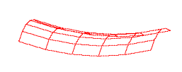

This document describes a 3D Bezier surface patch viewing program. It has been written by Chien Hsiung, who has kindly donated this version to the public domain. He is currently working on a fully featured GUI to allow greater control over the program. Contact him at chsiung@ecrc.gatech.edu if you're interested in his next version.
This program is a 32 bit program for PCs. It requires MS Windows 95 or Windows NT to run. It utilizes the OpenGL library of graphics routines to display the Bezier surfaces. If you do not have the 2 DLL files which allow you to display OpenGL graphics on your PC, you can get them here. Copy both of these files to your \Windows\system\ folder.
You need to download three files: the executable, and two data files, one for each type of deformation possible.
You need to setup a shortcut (for Win95) or an icon (for WinNT) which calls the executable and then provides the name of the data file. For example,
"C:\Patch DEMO\BezShow.exe" bowl.dat
works on Win95 if you've downloaded the executables and data files to the Patch DEMO directory.
The data files are human readable, and can be edited by hand. (Your other option if you want to change the shape of the surface patch is to manipulate the control points with the program, and ask the program to write the data file to disk.) Please note, however, that in order to remain a quadratic surface patch, you must choose your control points p0, p1, p2, and p3 for each curve such that:
p1=(p0 + 2p*)/3
p2=(p3 + 2p*)/3
where p* is the point where the end tangents intersect. If you do not satisy this condition, you have a bezier curve, not necessarily a quadratic curve.
Also note that the four interior control vertices are all co-planar to allow the shape of the surface patch to be completely determined by the bounding curves.
The two header sections of the data file are fairly self-explanatory. The "bounding box" is just that- the xyz max and minimum values. The "pivot" is the location of the pivot point as the patch is interactively rotated by the mouse.
Launching the software will present you with two windows- a display window and a textual information window. The textual window does not accept input- to enter a command into the program, make sure the display window is the active window.

|

|
|
|
|
The display window initially shows a wireframe of the surface patch as seen from the normal to the patch. Click and drag with the mouse to rotate the patch. Typing 'h' into the display window brings up help information in the textual information window. This message is reproduced below:
Total # of Patch(s)=1
Subdivision = 5
** Press 'h' for help

[Help Message]
c = toggle (C)ontrol hull
a = toggle control point (A)djusting (when Control Hull is On)
h = print this (H)elp message
m = toggle s(M)oothing
n = toggle (N)ormals
r = (R)eset view
s = toggle (S)hading / wire-frame mode
S = (S)ave the current matrices (will ask for filename)

Up/Down Arrows = Change Active Patch
Right/Left Arrows = Change Active Node on Patch

Not in Adjusting Control Point Mode:
    Left Mouse button Move = Rotations
    Right Mouse button Move = Scale

In Adjusting Control Point Mode:
    Left Mouse button Move = X - Y Drag
    Right Mouse button Move = Z Drag
You should now be able to view the provided example PWBs. Enjoy!

<Why Analyze> <Analysis Details><PM Spec> <ABB Spec> <PBAM Spec> <References>
This page last modified on: July 6, 1996